AMDAPTM Series - Metal Powders for 3D Printing -
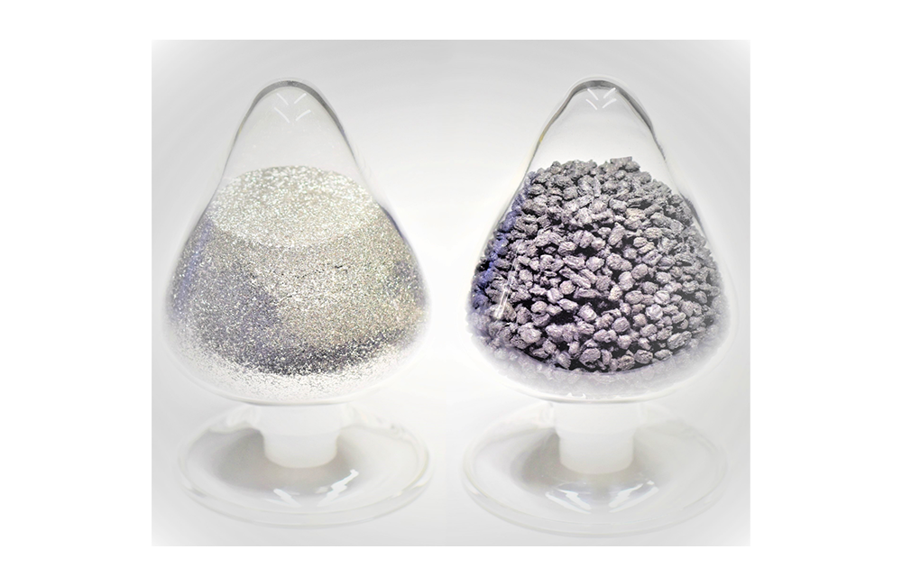
- Metal powders for 3D printing by SLM
Die steel-based powder for printing large products AMDAPTM LTX
AMDAPTM LTX have been developed by adjusting chemical composition of metal powder suitable for additive manufacturing for large products exceeding 150 x 150mm by SLM.
Characteristics
- Powders produced by gas atomization and have low oxygen content and high flowability.
- Reduces internal strain during molding compared to H13 and AMDAPTM HTC, suitable for large-sized products.
- Thermal conductivity is equivalent to SKD61. Mold performance is expected to be similar.
- Co is not contained.

Fig.1 Characteristics of AMDAPTM LTX compared to other powders.
Major applications
- Pins and inserts etc. with cooling holes
Typical chemical composition and hardness range
| Typical chemical composition(mass%) | Hardness (HRC) |
|||||
| C | Si | Ni | Cr | Mo | V | |
| 0.25 | 0.1 | 6 | 5.2 | 1.2 | 0.4 | 40~52 |
Particle size
| Particle size (µm) |
| -53/+25 |
The mechanisms of low internal strain
By designing alloys with a martensitic transformation starting temperature
(the temperature at which they become hardened by quenching) lower than the molding temperature,
the material is not quenched during the molding process, and is soft and less prone to distortion accumulation.
After the molding process is completed, the entire molding part is simultaneously quenched and hardened.
H13, AMDAPTM HTC:Hardening starts between 300℃ to 400℃ after quenching.


Fig.2 Strain improvement mechanism of AMDAPTM LTX.
Influence of base plate temperature on internal strain
Stable low strain can be obtained by heating the base plate to 160℃ or higher.
If heating to 160℃ or higher is impossible, adjust the temperature around 50℃ to reduce strain.

Fig.3 Relationships between preheating temperature of base plate and amount of deformation of 3D-printed sample.

Fig.4 The overview of 3D-printed sample.

Fig.5 Schematic diagram of the deformation measurement method.
Properties

Fig.6 Tempering Hardness of AMDAPTM LTX compared to H13.

Fig.7 Thermal conductivity of AMDAPTM LTX compared to H13 and maraging steel.

Fig.8 Relationship between hardness, 0.2% proof stress, and tensile strength.

Fig.9 Relationship between hardness and Charpy impact value.
The heat check resistance of AMDAPTM LTX is equivalent to that of SKD61 steel.

Fig.10 the results of the Heat cracking test.

Fig.11 Magnified view of the notch area when heat checking occurs

Fig. 12 Schematic diagram of the heat cracking test.
Nitriding properties are almost equivalent to those of SKD61.

Fig. 13 Hardness distribution from surface layer after nitriding.
Heat checking resistance of the AMDAPTM LTX 3D-printed mold evaluated by a die casting machine
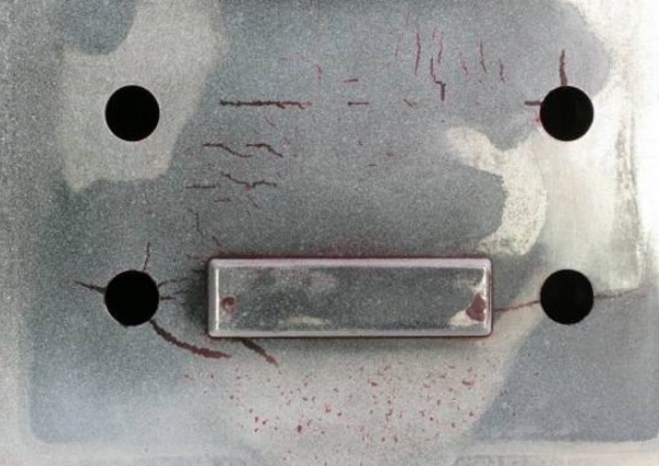
The AMDAPTM LTX 3D-printed mold shows less number of heat checking cracks than that of maraging steel at the same hardness condition.
The reason for this result is that the higher thermal conductivity of AMDAPTM reduced thermal stress.
Maraging steel(51HRC)
AMDAPTM LTX(51HRC)
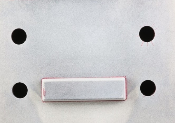
Fig. 14 Comparison of the appearance of the test molds after penetrant testing (at 10,000 cycles)
Table 1. Die casting conditions
| Cast AI-alloy | ADC12 | Injection velocity | 1.6m/s |
| Weight of a cast | 600g | Casting pressure | 65MPa |
| Temperature of molten AI-alloy | 685℃ | Lubricant spray time in a cycle | 3s |
3D printing parameters
The data shown in Table 2 are 3D printing process parameters for GE Additive’s Concept Laser M2 machine.
When using other equipments, please refer to the table for optimizing conditions.
Please feel free to ask our Metal Powder Department about the process parameters.
| Part | Laser power (W) |
Laser spot diameter (μm) |
Scanning speed (mm/s) |
Hatching distance (mm) |
Layer thickness (μm) |
|
| Product | Inside | 300 | 180 | 600 | 0.13 | 50 |
| Contour*5 | 150 | 100 | 300 | ― | 50 | |
| Downskin*6 | Inside | 380 | 180 | 950 | 0.13 | 50 |
| Contour*5 | 125 | 100 | 750 | ― | 50 | |
| Supporting part | 150 | 100 | 700 | ― | 50 | |
The recommended laser scanning pattern is a checker-board type and the recommended base plate temperature is 200°C.
*4
Recommendations are for reference only and do not guarantee the aforementioned quality of mechanical properties and fatigue strength, etc.
*5
Process parameters for forming outline part 2 times irradiating laser on the contour part (2nd time is shifted 70 μm inward from 1st time) can reduce defects in the border between contour part and inside part.
*6
Since the surface of the downskin part tends to be rough, the surface roughness can be reduced by applying the specific molding parameters shown in Table 2
(Note : Downskin contour area should be irradiated by a single laser.)

Fig.15 Image of laser irradation (2times) to form the outline part.

Fig.16 Defects in the border between outer part and inside part.

Fig.17 The comparison of cross-sectional roughness of the downskin part.(the angle of the downskin:30°)

Fig.18 The comparison of the surface roughness of the downskin area by 3D measurement.
Mold manufacturing process using AMDAPTM LTX
AMDAPTM LTX can be quench-hardened during 3D printing.
Base plate temperature is recommended to be higher than 160℃.
Tempering is recommended to be conducted more than twice, and temperature of the last tempering is reccomended to be higher than 550℃.

Fig.19 Mold manufacturing process of AMDAPTM LTX.
The example of 3D-printed mold
No cracking was observed both as 3D-printed and after tempering at the temperature at which maximum hardness is obtained (550℃).
Large products exceeding 150 x 150mm can be modeled.

Fig.20 The example of 3D-printed sample of AMDAPTM LTX.
Example of 3D-printed mold by Ifuku Seimitsu Co., Ltd.
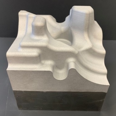
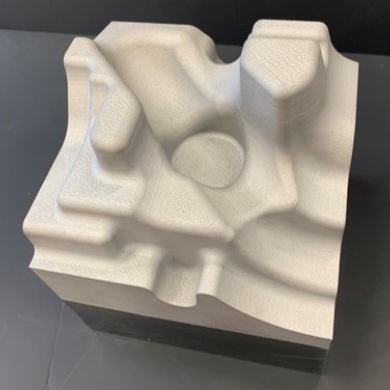
| 3D printing | Ifuku Seimitsu Co., Ltd. (Click here to the website.) |
| Printer | Precision Metal 3D Printer OPM250L Manufactured by Sodick Co., Ltd. |
| Size of the 3D-printed mold (mm) |
140×140×100 |
| Material | AMDAPTM LTX (Base plate:SKD61) |
Technical data
Disclaimer and copyright
The figures in this document are typical values based on the results of our tests and there is no guarantee that the figures presented will be achieved when the products are used.
The information in this document is subject to change without notice.
Please contact us for the latest information.Any unauthorized distribution or reproduction of the content of this document is prohibited.
AMDAP and LTX are trademarks or registered trademarks of Daido Steel Co., Ltd.


